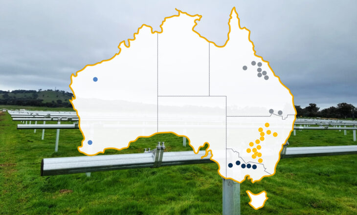
In my previous post, Exploring Bifacial 2MIL for LCOE Optimization, I touched on the various formats ARRAY has used for bifacial mounting. I also talked about how we’re exploring every option and zeroing in on whether our standard format, 1 Module In Portrait (1MIP), is the best way to give our customers optimized bifacial solar production.
In this post, I’ll discuss in more detail how we’ve been testing 1MIP bifacial module performance and validating them against other third-party results—specifically, how we’re examining the pros and cons of the two most popular bifacial formats: 1MIP and 2 Module In Portrait (2MIP), and which is the better format for bifacial gains.
1MIP vs 2MIP Bifacial Solar Mounting
To quickly define terms, 1MIP stands for 1 module-in-portrait and 2MIP for 2 modules-in-portrait. A 1MIP bifacial panel is mounted across the solar tracker, while 2MIP has two separate panels on either side of the tracker post and torque tube.
With bifacial PV, it’s important to estimate how much light you’re receiving on the front side of the arrays, but also to calculate how much irradiance you get on the backside. Bifacial energy gains come from an increase in the total irradiance.
Our engineers have released third-party validated data showing that 1MIP collects more light on the backside than 2MIP. Using this 2D model, they were able to calculate how much of the ground is shaded, how much of the ground gets light from the sun, and how much of that reflected light the PV modules capture.
Back-to-front irradiance ratio (BFIR) describes the available light for bifacial and is a good measure of the total available bifacial resource. BFIR is dependent on the albedo, climate, ground-coverage ratio (GCR), and tracker aspect ratio (row height/width).
What our engineers are finding falls in line with PVsyst calculations and many other published white papers in the industry, all of which show higher BFIR for 1MIP systems than for 2MIP systems.
Shading Losses Are Not Zero, Even for 2MIP
There’s been talk about the potential shading of bifacial panels in a 1MIP format, and ideas that 2MIP solves this problem by spacing the panels out on either side. ARRAY partnered with PV Lighthouse to study this topic in detail. PV Lighthouse’s SunSolve™ software is widely regarded as one of the most advanced 3D ray-tracing solutions for PV.
One of the important findings from PV Lighthouse’s study was that it is in fact not a good idea to have a gap between the east and west panels. Any gap between the east and west panels effectively increases the ground coverage ratio when the row-to-row spacing is fixed, and the energy loss from the longer backtracking required ends up outweighing any benefit from the reduced shading on the back. So a zero east-west gap turns out to be the optimal setup for modules on 2MIP trackers, in which case the structural shading losses become very similar to the 1MIP trackers.
PV Lighthouse’s ray-tracing calculations further show that the mismatch loss from a torque tube shading is small, in the order of 0.2%. This is due to the backside irradiance arriving at the module at high angles from both sides of the torque tube, resulting in a soft shadow that causes only very small cell-to-cell total irradiance mismatch.
We carried out third party testing to see if the structural shading under high-albedo conditions can cause problems such as hot spots or bypass diode activations, but we were not able to reproduce such issues in realistic setups where the array is continuously maximum-power-point (MPP)-tracked with an inverter. There had been a prior work showing hot spots appear due to torque tube shading in a short-circuited module, but this setup is not representative of what happens in the real-world conditions.
Speculation that’s often brought up is that the height from the ground makes a big difference in BFIR. Three-dimensional ray-tracing studies, as well as two-dimensional view-factor approaches (possible with PVsyst) reveal that this notion is simply not true. It is the aspect ratio (ratio of the row height to the row width) that drives the BFIR, under the same conditions of GCR and albedo.
Sunlight arrives at the ground through the openings between the tracker rows, but a substantial portion of the ground-reflected light escapes back to the sky through those very openings. It is the aspect ratio, and not the absolute row height, that determines the ratio of captured versus lost light.
In the realistic ranges of row height, determined by material costs and workability on field, the aspect ratio is almost always higher for 1MIP trackers than 2MIP trackers, which in turn results in the BFIR being almost always higher for the 1MIP trackers. To match the aspect ratio of the shortest 1MIP tracker, the 2MIP tracker needs to be built with the torque tube at nearly 3 meters!
There’s More to Bifacial Gain Than 1MIP vs 2MIP
All things considered, 1MIP comes out on top. 1MIP starts out with a higher bifacial solar resource (BFIR) than 2MIP, and the subsequent losses such as structural shading and mismatch are similar for both setups.
Utility-scale PV projects, however, should not select trackers based on the expected difference in bifacial gain alone. Installation costs, O&M and a trackers wind management approach can have a significant impact to a project’s LCOE and must be considered. Stay tuned for a follow-up where I’ll go more deeply into these topics.
To learn more about these topics tune in on February 20, 2020 for a free webinar with Greentech Media. Register HERE.
Click here for other articles by this author